
Understanding Piping Isometric Drawings: A Comprehensive Guide
Piping isometric drawings are essential documents in the field of mechanical engineering, particularly in industries such as petrochemicals, oil and gas, and power generation. These detailed representations serve as a vital communication tool, providing a three-dimensional view of a piping system’s layout, components, and connections. This guide will delve into the intricacies of piping isometric drawings, their importance, the creation process, and their significance in the construction and maintenance of industrial facilities.
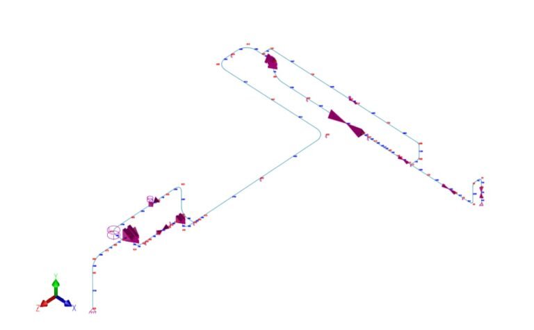
What are Piping Isometric Drawings?
A piping isometric drawing is a technical illustration that presents a 3D representation of a piping system. Unlike orthographic drawings that show different views (front, side, and top) separately, isometric drawings combine these views into a single, easily understandable image. This perspective provides a clear visualization of how pipes, valves, fittings, and other components are arranged in three-dimensional space.
Importance of Piping Isometric Drawings
- Clarity and Comprehension: Isometric drawings offer a realistic portrayal of the piping system, allowing engineers, designers, and technicians to easily understand the spatial relationships between components.
- Accuracy in Fabrication and Installation: These drawings serve as a blueprint for fabricators and installers. They provide precise information on pipe lengths, angles, and connections, ensuring that the actual installation matches the design specifications.
- Conflict Detection: By examining the isometric drawing, potential clashes or interferences with other elements of the facility (such as structural components or equipment) can be identified before construction begins, preventing costly rework.
- Material Takeoff and Procurement: Isometric drawings assist in calculating the quantity and specifications of materials required for construction. This aids in procurement and cost estimation.
- Regulatory Compliance: Many industries have strict codes and standards for the design and installation of piping systems. Isometric drawings help ensure compliance with these regulations.
Components of a Piping Isometric Drawing
Pipes: Represented by single or double lines, pipes are labeled with their nominal size, schedule, and material specifications.
Fittings: These include elbows, tees, reducers, flanges, and valves. Each fitting is depicted with its specific type, size, and orientation.
Valves: Shown in various positions (open, closed, or partially open), valves are labeled with their type, size, and class.
Special Items: These may include instruments, strainers, expansion joints, and other unique components relevant to the system.
Dimensions: Distances between components are specified to ensure accurate fabrication and installation.
Tags and Labels: Each component is assigned a unique identifier or tag that corresponds to a bill of materials.
Notes: Additional information, such as material specifications, pressure ratings, and special instructions, may be included.
North Arrow: Indicates the orientation of the drawing about the cardinal directions.
Scale: Specifies the ratio of the drawing’s size to the actual size of the components.
Creating Piping Isometric Drawings
The process of generating a piping isometric drawing involves several steps:
- 3D Modeling: A 3D model of the piping system is created using specialized software. This model serves as the basis for generating the isometric drawing.
- View Extraction: Views of the 3D model are extracted to create the isometric view, which includes all necessary components and connections.
- Annotation and Labeling: Each component is labeled with its respective tag, and additional information is added as needed.
- Dimensioning: Distances and dimensions are added to provide fabrication and installation instructions.
- Review and Approval: The drawing is reviewed by relevant stakeholders for accuracy and compliance with design specifications.
Conclusion
Piping isometric drawings are indispensable tools in the design, construction, and maintenance of piping systems in various industries. Their ability to provide a clear, three-dimensional representation of complex systems facilitates accurate fabrication and installation, reduces the likelihood of conflicts, and ensures compliance with industry standards. By understanding the components and creation process of isometric drawings, engineers and professionals in the field can effectively communicate and execute piping projects with precision and efficiency.
We also provide piping support design